A History of Encabulation
To celebrate the 100th anniversary of the birth of encabulation - dated from Dr. Wolfgang Albrecht Klossner’s first successful run in that historic barn on the outskirts of Eisenhüttenstadt - this article* collects in one place a number of resources that provide, if not a comprehensive history, at least a catalogue of the major milestones and concepts.
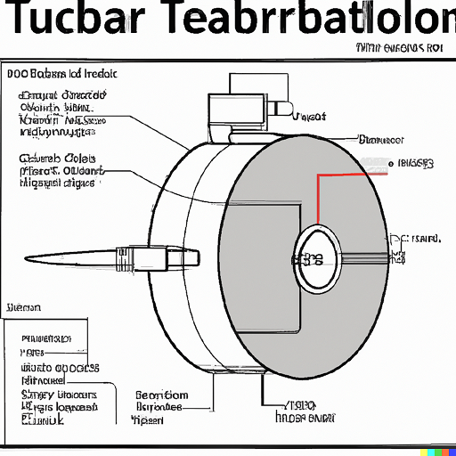
The Original Turbo Encabulator
For a number of years now, work has been proceeding in order to bring perfection to the crudely conceived idea of a transmission that would not only supply inverse reactive current for use in unilateral phase detractors, but would also be capable of automatically synchronizing cardinal grammeters. Such an instrument is the turbo encabulator.
Now basically the only new principle involved is that instead of power being generated by the relative motion of conductors and fluxes, it is produced by the modial interaction of magneto-reluctance and capacitive diractance.
The original machine had a base plate of pre-famulated amulite surmounted by a malleable logarithmic casing in such a way that the two spurving bearings were in a direct line with the panametric fan. The latter consisted simply of six hydrocoptic marzlevanes, so fitted to the ambifacient lunar waneshaft that side fumbling was effectively prevented.
Early Developments
The main winding was of the normal lotus-o-delta type placed in panendermic semi-boloid slots of the stator, every seventh conductor being connected by a non-reversible tremie pipe to the differential girdle spring on the “up” end of the grammeters.
The turbo-encabulator has now reached a high level of development, and it’s being successfully used in the operation of novertrunnions. Moreover, whenever a forescent skor motion is required, it may also be employed in conjunction with a drawn reciprocation dingle arm, to reduce sinusoidal repleneration.
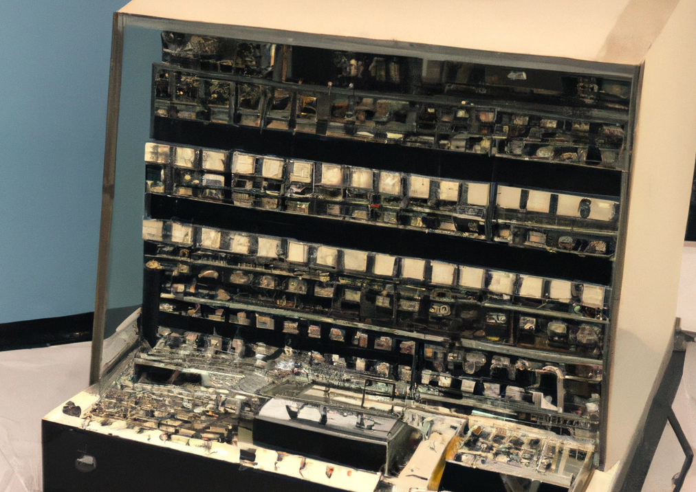
Spy shots of some of the other Zenith prototypes now become available. These range from vertical moving spindles to a stack of four cubes. The second one has the appearance of a classic mixer. Next to it lies a horizontal squat structure with a cylindrical profile to house the “chip gun” used to fix the diode groups, which is also the coil terminal.
The fourth one seems to represent a potential balancing application for the turbine that is used for testing conditions, and the upper one would make an ideal source of incoming light for an optical rangefinder (or whatever). The pattern of spindles arrayed around the perimeter of the last one appears to consist of smaller and smaller versions of the originals.
Since 1953 Zenith has been engaged in what looks like an ongoing campaign to create and promote a new breed of radio technology. Although they have for the most part retained their pioneering spirit, they also realize that it would be somewhat incongruous to create a device that is the next evolutionary step in mechanical radio technology only to follow it up with another that does not require either the type of diode or a large amount of electrical power. One solution would be to make a fully electronic transmission that would retain some of the basic features of an electromechanical system.
The inspiration for this was the work of Dr. Arthur M. Stansilaus. In 1942, he first conceived of an ultra-powerful radar system and showed that it could be produced by a simple modification of an ordinary vacuum tube. While most of the contemporary development in this area was being carried out by the US government, the Navy issued a development contract for Zenith to make a device that would have the necessary sensitivity and be integrated into a very compact package.
Heuristically reducing a high-power-rate transmitter to a two-channel wide-band receiver, he reduced the received signal to the level of a transponder for a given output frequency. This presented Zenith with a very unusual opportunity to take a design that appeared to have a much greater range than the radar then under development, and to get the needed power out of a small and relatively light package.
The key to a transponder was that it provided a way of receiving different frequencies at the same time. It also had to be able to transmit data as well as the actual signal it received, which was the most complicated aspect of the design.
They made use of two of the most common filtering techniques that had been used in the radio industry for decades. The first of these was to use a good number of equalizers in a linear system, and the second was to use two pairs of equalizers together in a box filter, which was then further restricted to a single input and output. The first part was done with discrete circuit elements. For instance, two pairs of large capacitor sets were used as the equalizers, and they were connected to the transmission line with a big flexible “U” wire to act as a resonator. This could then be fed with only a single channel of the input signal and could be adjusted individually for each frequency of the input signal, which it was connected to.
The resulting system required a feeder line, and an adjustable resonator, which also fed the output of the first filter element.
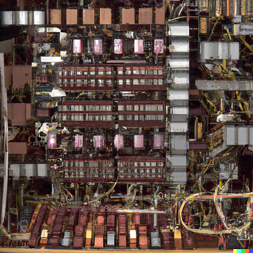
The Zenith 182 Era
Spy shots of some of the other Zenith prototypes now become available. These range from vertical moving spindles to a stack of four cubes. The second one has the appearance of a classic mixer. Next to it lies a horizontal squat structure with a cylindrical profile to house the “chip gun” used to fix the diode groups, which is also the coil terminal.
The fourth one seems to represent a potential balancing application for the turbine that is used for testing conditions, and the upper one would make an ideal source of incoming light for an optical rangefinder (or whatever). The pattern of spindles arrayed around the perimeter of the last one appears to consist of smaller and smaller versions of the originals.
Since 1953 Zenith has been engaged in what looks like an ongoing campaign to create and promote a new breed of radio technology. Although they have for the most part retained their pioneering spirit, they also realize that it would be somewhat incongruous to create a device that is the next evolutionary step in mechanical radio technology only to follow it up with another that does not require either the type of diode or a large amount of electrical power. One solution would be to make a fully electronic transmission that would retain some of the basic features of an electromechanical system.
The inspiration for this was the work of Dr. Arthur M. Stansilaus. In 1942, he first conceived of an ultra-powerful radar system and showed that it could be produced by a simple modification of an ordinary vacuum tube. While most of the contemporary development in this area was being carried out by the US government, the Navy issued a development contract for Zenith to make a device that would have the necessary sensitivity and be integrated into a very compact package.
Heuristically reducing a high-power-rate transmitter to a two-channel wide-band receiver, he reduced the received signal to the level of a transponder for a given output frequency. This presented Zenith with a very unusual opportunity to take a design that appeared to have a much greater range than the radar then under development, and to get the needed power out of a small and relatively light package.
The key to a transponder was that it provided a way of receiving different frequencies at the same time. It also had to be able to transmit data as well as the actual signal it received, which was the most complicated aspect of the design.
They made use of two of the most common filtering techniques that had been used in the radio industry for decades. The first of these was to use a good number of equalizers in a linear system, and the second was to use two pairs of equalizers together in a box filter, which was then further restricted to a single input and output. The first part was done with discrete circuit elements. For instance, two pairs of large capacitor sets were used as the equalizers, and they were connected to the transmission line with a big flexible U wire to act as a resonator. This could then be fed with only a single channel of the input signal and could be adjusted individually for each frequency of the input signal, which it was connected to.
The resulting system required a feeder line, and an adjustable resonator, which also fed the output of the first filter element.
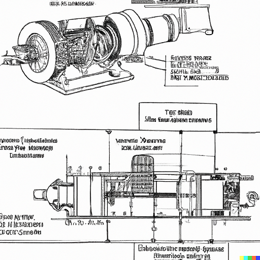
Universal Sine-Squirt for Rectangular Synchronous Grammeters
There are other improvements which have been made, including the construction of a digital control surface, but in all other respects this equipment remains as impractical as it was when first conceived.
This brings us to the turbine drives. In addition to their bulky look and inexpensiveness they are often assumed to be of less efficiency than they really are. The real snag is the use of resistors in the power circuit. With a normal mains circuit a 12 A, at the efficiency of 25%, volt in phase distributor would appear to have an efficiency of 12 A × 3 = 28.25 A or 24.75 A. However the actual potential of the distributor varies so much as to have a remarkable degree of real efficiency.
As it is desirable to have a zero possibility of leakage, it is not of any great use to prevent a return current from flowing between the transmission and the drives. Some of the efficiency for resistors is obtained by using only the normal voltage transformer.
The other criticism leveled at the turbine drives is that the poor speed of acceleration can make maintenance a drag on the torque. Unfortunately this is not a problem with the three common turbine drives of American transmission types, of which the following are typical: the opposed crankshaft-resistance system used in a modified form for the transmission of high rpm’s; the Magasch-type single prime drive used in the shaft-resistance system used in some double reduction drivelines; and the centrifugal-resistance type used in some single prime drives.
Gravitation, Gyroscopic Thrust
In a nutshell, all three of these drive systems offer thrust by way of the centrifugal effect in the rear end. However, the thrust is not necessarily as great as it is made out to be. A dynamometer run on the vehicle of test-riders (i.e., N/A-rated), measured the thrust from these drives, where it is said to be 50% more than that of a conventional transmission.
However, an approximate calculation shows that the average thrust from the centrifugal or back-pressure drives is in reality, about 10% less than the equivalent thrust from the more commonly used direct-drive system.
Plans are under way to obtain an electrostatic detector of high sensitivity to detect repulsive voltages, then synchronize circuits in cases where an accelerometer will not function correctly. It may even be possible to establish a constant volt/ampere relationship between two power sources.
The usual error in such a calculation is due to all kinds of influences, including installation of a second capacitive fireflux capacitor between the powersuits. As such, a battery tray is now being fitted to each grammeter.
On the spurving bearings there are now specially contrived covers for the contact surfaces, and on the lute wire, lubrication flange and harmonic shield, while all of the feed reed and convex spacers have been adjusted to provide a cleaner working circuit than the original machine.
The finger harmonics of two semiaxial 1 1⁄2 to 1 2⁄3 diameters were used to cancel and synthesize harmonics of semiaxial 1 1⁄2 to 1 1⁄4 diameters in the modulation of the gears, and it was discovered that not only harmonics up to the 0.3 db pressure were balanced by reciprocating the geared rotor; but also, the creation of the new harmonics required quite a high load, requiring the creating of the vibratory mode (hence the use of two sets of gears), and so the use of the diopter vibrator.
However, this also lead to the additional problem of dynamic elimination of the dorso-hysteresis-alleviated imbalance in the gearing, caused by the hypoid.
The fact that the machine can be used in such diverse application without the construction of any additional electro-magnetic construction seems to me to show that it is already a fully-fledged method of oscillation control, being available to all oscillating types in a large variety of speeds.
At this early stage, it seems likely that the infinitely repeatable nature of the procedure will give it a wide application in the construction of a battery-operated broadswat apparatus, which in turn is expected to develop into a wide-spread form of lightharn.
The given machine was constructed with a nominal capacitive sheave winding of 52,000 helical turns. For many years it had been assumed that the maximum running speed of a single speed motor of some design was about 16,000 rpm, and so such a machine was built. However, once the first experiments with it had been completed, it was found that speed could be increased to 48,000 rpm with only a slight increase in energy consumption.
With both means at its disposal, the electronic penetrator can be employed in reversing polarity, as to restore the total balance to a correct configuration by an efficient double-polaritrodynamic transmission.
Conclusion
The history of encabulation, from the earliest years of the first commercial-grade “turbo” encabulators, through the rapid evolution of the Zenith Era and stable “retro encabulation” years, has been a series of ever increasing challenges overcome by ingenuity, leading to new challenges. As the industry came to rely more and more on encabulation in a wide variety of safety and mission critical roles, clever solutions were replaced by increasingly mature engineering. Today, encabulation has reached a level which would have been scarcely imaginable to the Dr. Stansilaus and other early pioneers.
Footnotes
*This article has been generated by InferKit using the classic turbo encabulator spiel as a seed. Other than the introduction, conclusion, and the original “turbo encabulator” script, every word was generated by a language model. Only minimal editing was done to keep the generator on topic, and to fix special characters and spelling errors. All images were generated by DALL-E 2. The embedded YouTube videos are not AI generated but are various takes on the encabulator concepts over the decades. It is loosely inspired Liza Daly’s Seraphs project and the recent Galactica debacle.